
7 Tips for Choosing the Best Wired Push Button?

Choosing the right Wired Push Button can seem simple until a machine stops responding in a dusty workshop. A button may look durable, yet its contacts, housing, and mounting method determine how reliably it performs. I have seen small design details create larger maintenance problems, especially when operators press controls hundreds of times each day.

This guide presents seven practical tips for evaluating a Wired Push Button before purchase. It considers contact configuration, voltage and current ratings, switching life, environmental protection, terminal quality, installation space, and operator safety. These details matter in control panels, access equipment, test benches, and industrial machinery. Check the datasheet carefully. Marketing language should never replace verified specifications.

A dependable button should match the circuit, not merely fit the panel hole. Look for clear wiring diagrams, credible testing information, and consistent manufacturing quality. A sealed model may resist dust and moisture, but it still needs correct installation. Even an experienced buyer can overlook cable strain or insufficient clearance. That is worth remembering.

The following advice combines practical selection experience with basic electrical engineering principles. It also highlights common assumptions that deserve a second look. The cheapest option may cost more after repeated failures, while the most rugged model may be unnecessary for a clean indoor cabinet. The best choice depends on the application, maintenance expectations, and real operating conditions. Assess the details before pressing the order button.
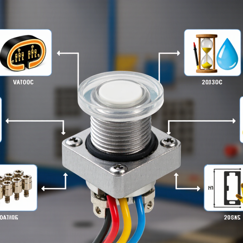
7 Tips for Choosing the Best Wired Push Button?

Define Load, Voltage, and Duty Cycle Before Comparing Wired Push Buttons

Choosing a wired push button starts with the load, not the appearance. Identify what the button will switch: a small signal, a lamp, a relay coil, or a motor circuit. A button rated for five amps may not handle a motor’s starting surge safely. Check both the steady current and the inrush current. Write these values down.

Voltage matters just as much. Confirm the circuit’s AC or DC type, operating voltage, and maximum switching voltage. DC loads can create stronger arcs when contacts open. I have seen compact buttons fail early because their current rating was checked without checking voltage. That shortcut is easy to make. It is also costly.

Duty cycle describes how often and how long the button operates. A control used twice daily has different demands from one pressed every few seconds. Estimate presses per hour, contact time, and total service life. Then consider dust, moisture, vibration, and the enclosure around the switch. A laboratory rating may not match a warm, oily workshop. Compare contact material, terminal strength, and wire compatibility after defining these conditions. Do not rely only on a product label. If the load is inductive, test the complete circuit with suitable suppression. My own comparisons became more accurate after recording temperature and contact behavior during repeated switching. I still leave a safety margin, because real installations rarely behave perfectly.

Check IEC 60947-5-1 Ratings, Contact Forms, and Switching Categories

7 Tips for Choosing the Best Wired Push Button

Tip 1

Check IEC 60947-5-1 ratings before comparing appearance or price. Confirm rated insulation voltage, thermal current, and operational voltage. These figures show whether the button suits your control circuit. A rating that looks sufficient may fail under frequent switching.

Tip 2

Match the contact form to the control logic. A normally open contact closes when pressed. A normally closed contact opens during operation. Changeover contacts provide both options. In panel inspections, I have seen wiring errors caused by confusing terminal markings. Check the diagram, not just the button shape.

Tip 3

Review the switching category carefully. AC-15 commonly covers electromagnetic control loads. DC-13 applies to electromagnets and similar direct-current loads. Motors, lamps, and solenoids may require different assessments. The load’s inrush current matters. A button can pass a simple continuity test and still wear quickly in service.

Tip 4

Consider the real installation environment. Dust, moisture, vibration, gloves, and repeated impacts affect selection. Check the enclosure rating and mechanical endurance. Choose clear terminals and suitable wire capacity. I sometimes focus too much on electrical ratings and overlook cable access. That mistake deserves a second look. Reliable selection comes from comparing the standard, load data, wiring method, and documented test conditions. Always verify the current datasheet before installation.

Match IEC 60529 Protection Levels, Including IP65 for Dust and Water

Choosing a wired push button starts with the installation environment, not the appearance. Check seven details: contact rating, voltage, actuation force, mounting depth, cable entry, emergency access, and enclosure protection. IEC 60529 defines IP ratings through controlled dust and water tests. IP65 means dust-tight protection and resistance to water jets. It does not mean safe immersion.

A practical selection should match real exposure. An IP65 button suits dusty workshops, outdoor control panels, and washdown areas with moderate spray. It may fail near high-pressure cleaning, chemicals, or standing water. For those conditions, compare higher protection levels and verify the test conditions. The second digit matters. A higher number is not automatically better for every installation.

Workplace reliability also deserves attention. The U.S. Bureau of Labor Statistics reported 2.6 million nonfatal private-industry injuries and illnesses in 2023. A clearly visible, correctly positioned control can reduce hesitation during an incident, although no button replaces a complete safety system. Check the IEC 60529 declaration, test method, gasket quality, and cable gland compatibility. I still see teams trust an IP65 label without checking the panel opening. That is a costly shortcut. Also confirm switching capacity under the actual load, since small contacts can overheat when repeatedly switching motors. Test the button with gloves, dust, moisture, and poor lighting before approval.

Compare Mechanical Life Ratings, Such as 1 Million Operating Cycles

When choosing a wired push button, I examine its mechanical life rating before comparing appearance or price. A rating of one million operating cycles suggests strong physical endurance. It does not guarantee one million reliable electrical signals. The figure usually describes repeated pressing under controlled laboratory conditions. Real installations are less predictable.

Mechanical life measures how long the button structure may survive movement. Electrical life measures switching performance under a stated voltage and current. These figures can differ sharply. A button tested with a light load may last longer than one controlling a demanding circuit. Check the test conditions, actuator force, stroke distance, and switching load. Small details matter.

Consider the working environment too. Dust, moisture, vibration, and frequent side pressure can reduce service life. In field maintenance, I have seen buttons fail early because users pressed them at an angle. That mistake is easy to overlook. A million-cycle rating also needs context: a control used 200 times daily could theoretically reach that figure in more than 13 years, but wear may appear sooner. I would also inspect contact resistance, terminal strength, wiring protection, and available replacement access. The highest rating is not always the best choice. It may add cost without improving the actual application. Test a sample under realistic conditions when possible. Real use tells a different story.

7 Tips for Choosing the Best Wired Push Button

Mechanical life is the number of operating cycles a push button is designed to withstand before significant mechanical wear may occur. A 1-million-cycle rating is a useful benchmark for frequently operated controls, but the final choice should also consider contact rating, ingress protection, mounting style, and environmental conditions.

The chart compares representative mechanical-life ratings commonly specified for wired push-button designs. Ratings are application-dependent and should always be verified against the specific product datasheet. For high-frequency operation, choose a rating comfortably above the expected duty cycle.

Verify 22 mm Mounting, Terminal Wiring, Ergonomics, and Safety Compliance

7 Tips for Choosing the Best Wired Push Button?

Verify 22 mm Mounting, Terminal Wiring, Ergonomics, and Safety Compliance

Check the mounting hole before ordering. A 22 mm button needs a matching panel cutout and secure retaining nut. Measure the panel thickness, too. Tip two: inspect the terminal layout and wiring method. Screw, solder, and quick-connect terminals suit different maintenance routines. Mark each wire clearly. Do not guess.

Tip three: confirm the contact rating for your actual voltage and current. A switch rated for signals may not handle a motor circuit safely. Tip four: test the button with the intended gloves. A small actuator may feel awkward in cold, oily, or crowded work areas. Tip five: evaluate color, travel, and reset action. Clear feedback reduces accidental presses. Short travel is not always better.

Tip six: review ingress protection, insulation, and mechanical endurance data. Ask for test reports, not vague claims. Safety requirements differ by location and machine type, so check current local standards with a qualified professional. Tip seven: inspect the wiring after installation. Keep conductors away from sharp edges, heat, and moving parts. I have seen tidy panels hide loose terminals. That mistake deserves a second check. A final function test should include normal operation, emergency conditions, and power restoration.

7 Tips for Choosing the Best Wired Push Button? - Verify 22 mm Mounting, Terminal Wiring, Ergonomics, and Safety Compliance
Tip Selection Dimension Recommended Verification Practical Data or Typical Range Why It Matters Pre-Installation Check
1 22 mm mounting compatibility Confirm the required panel cutout, fixing method, anti-rotation feature, and available rear clearance. Typical control-panel cutout: approximately 22 mm nominal. The actual permitted cutout is defined by the product drawing and tolerance. A slightly incorrect hole size can cause loose mounting, rotation, difficult installation, or damage to the panel. Measure the panel opening, panel thickness, retaining-nut space, and the distance to adjacent components before ordering.
2 Contact function and electrical rating Select the required contact arrangement, such as normally open (NO), normally closed (NC), or a changeover contact. Common arrangements: 1NO, 1NC, or 1NO + 1NC. Resistive and inductive loads may have different current ratings; use the lower applicable rating. The correct contact configuration ensures that the button performs the intended control or emergency-interlock function. Compare the operating voltage, steady-state current, inrush current, load type, and switching frequency with the datasheet rating.
3 Terminal wiring and connection method Verify terminal identification, conductor size, stripping length, polarity requirements for illuminated versions, and tightening instructions. Typical terminals: screw-clamp, spring-clamp, solder lug, or quick-connect tab. Common quick-connect tab widths include 2.8 mm and 4.8 mm, but the exact size must be confirmed. Correct termination reduces loose connections, overheating, intermittent operation, and accidental short circuits. Use the specified wire size and ferrule or connector type. De-energize the circuit before wiring and apply the manufacturer’s stated terminal torque.
4 Actuator ergonomics Assess button diameter, profile, surface texture, travel, actuation force, and visibility for the intended operator. Typical considerations: larger or mushroom-style actuators are easier to hit quickly; low-profile buttons reduce accidental operation. Force and travel vary significantly by mechanism. Good ergonomics improve operating speed, reduce fatigue, and help prevent unintended activation. Test the button while wearing expected gloves and under the actual viewing, reach, and lighting conditions.
5 Environmental protection Check the ingress protection rating for the complete installed assembly, including the actuator, seal, panel, and wiring interface. Relevant rating: IP code under IEC 60529. IP ratings are written as two digits; the first addresses solids and dust, while the second addresses water protection. Moisture, dust, oil, and cleaning fluids can reduce insulation performance, cause corrosion, or impair mechanical movement. Match the rating to the enclosure, washdown method, temperature, humidity, vibration, and chemical exposure at the installation site.
6 Safety and compliance requirements Review the applicable electrical, machinery, enclosure, and emergency-stop requirements for the final equipment. Standards to consider: IEC 60947-5-1 for low-voltage control-circuit devices, IEC 60529 for IP ratings, and ISO 13850 for emergency-stop function where applicable. Compliance depends on the complete application and installation, not only on the push button itself. Confirm required approvals, creepage and clearance, protective earthing or insulation method, circuit category, and risk-assessment results.
7 Service life and maintenance Compare mechanical life, electrical life under the actual load, switching frequency, replacement availability, and inspection needs. Important distinction: mechanical endurance is tested without the electrical load; electrical endurance depends on voltage, current, load type, and switching conditions. A suitable service-life specification helps reduce unplanned downtime and prevents overestimating component durability. Record the installation date, provide wiring access, inspect terminals periodically, and replace components that show sticking, contact resistance, cracking, or heat damage.